Pico Power Monitor
Goal
The goal is to be able to measure the power consumption of my house and send that information to Home Assistant over MQTT where it will be logged.
Pre Requisite
To get a good general understanding on how a project like this works i would read these articles
Equipment
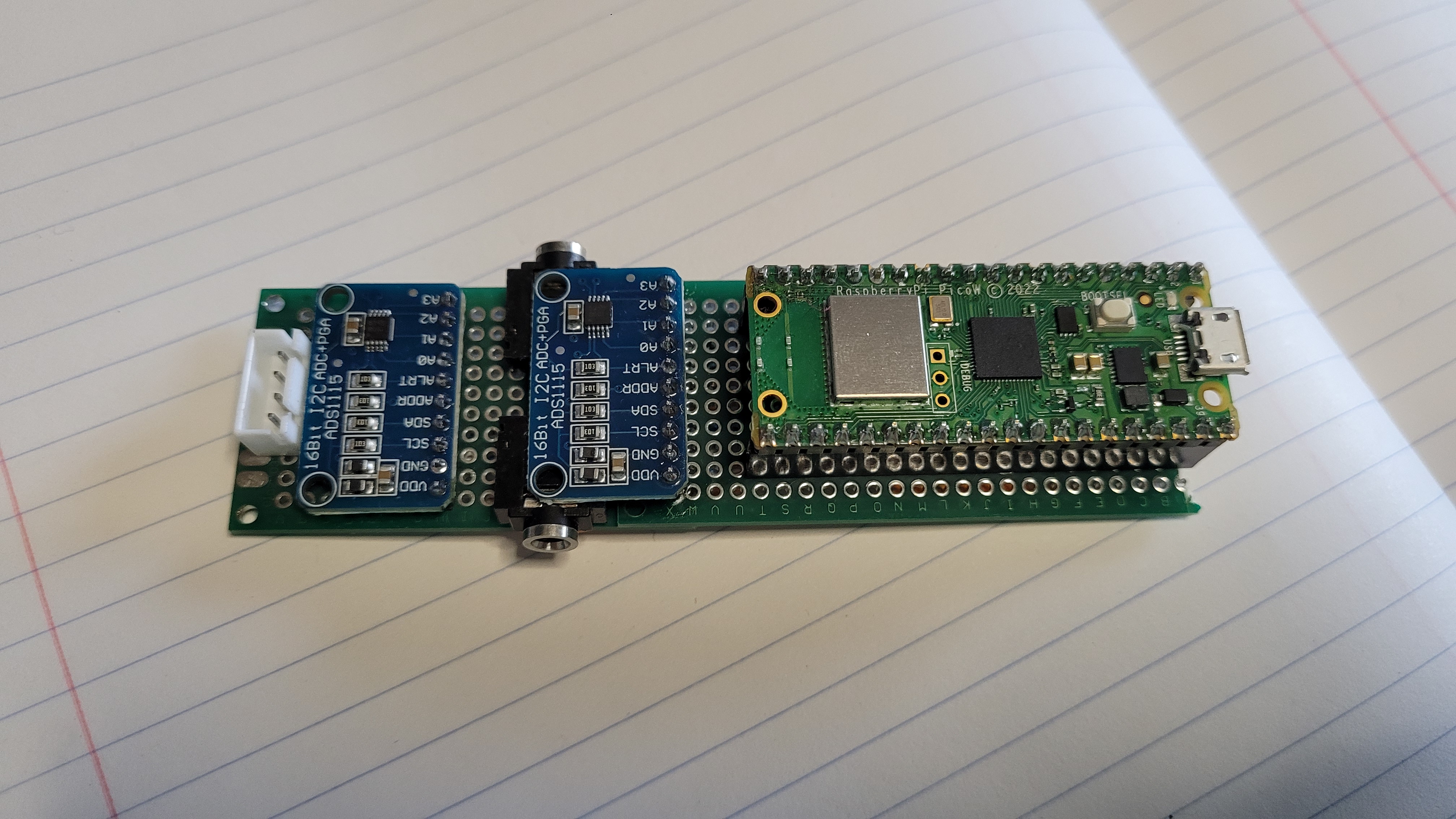
- raspberry pi pico W
- 2 TED 200A clamps
- 2 YHDC 100A SCT013 clamps
- 2 ADS1115 “External ADC”
Project Description
To measure power for a given building, one of the easiest way to accomplish this is to use CT “Current Transform” clamps. These wrap around the main wires in your house and as the name implies measure current. The signal that comes out of from a CT is clamp is going to be oscillating signal between some positive current or voltage to the inverse of that.
CT Clamps
TED 200A Clamps model QX-201-CT These clamps are nice because they can handle a high current and are fairly sturdy clamps. They also have a burden resistor inside of them which limits the peak to peak voltage to +-3V
YMDC SCT013-000 These clamps fairly cheap all around but they get the job done. There 100A and they don’t include a burden resistor. So you’ll have to supply one to give the clamp a given voltage range. There are lot of great example on using these clamps. Also openEnergyMonitor gave a extensive review of the product
ADC - ADS1115
Is a external ADC that can communicate over I2C. This ADC has 4 inputs but there muxed, so at any given time you can only one. But for this given example this adc has some benefits over most adc’s built into microcontrollers.
Upsides
- can take differential inputs
- 16 bit sensitivity
- relatively cheap
- very popular
Downsides
- relatively slow (max 860 samples per second “SPS”)
Layout
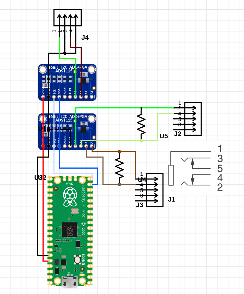
So when it comes to wiring up the board the most important thing comes down to making sure you have a burden resistor across the clamps that need it (so any clamp thats rated in amps). The next thing to consider is that the ADC can only handle +.3 of the input vcc that you give it. So if you feed it 3.3 in theory you could only input a voltage of 3.6 to it without damaging it. So even if you set the ADC to be +-4.096 if the vcc is set to 3.3 you won’t be able to get the full range. Lastly the ADS1115 can have 4 different i2c address based on the “ADDR”,”ALRT” pins. So if you need multiple ADS1115 you’ll need to properly set them.
Software for the Pico
Software can be found here. On the repo it should describe to you how to actually setup the project.
Home Assistant
Setting up
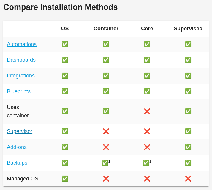
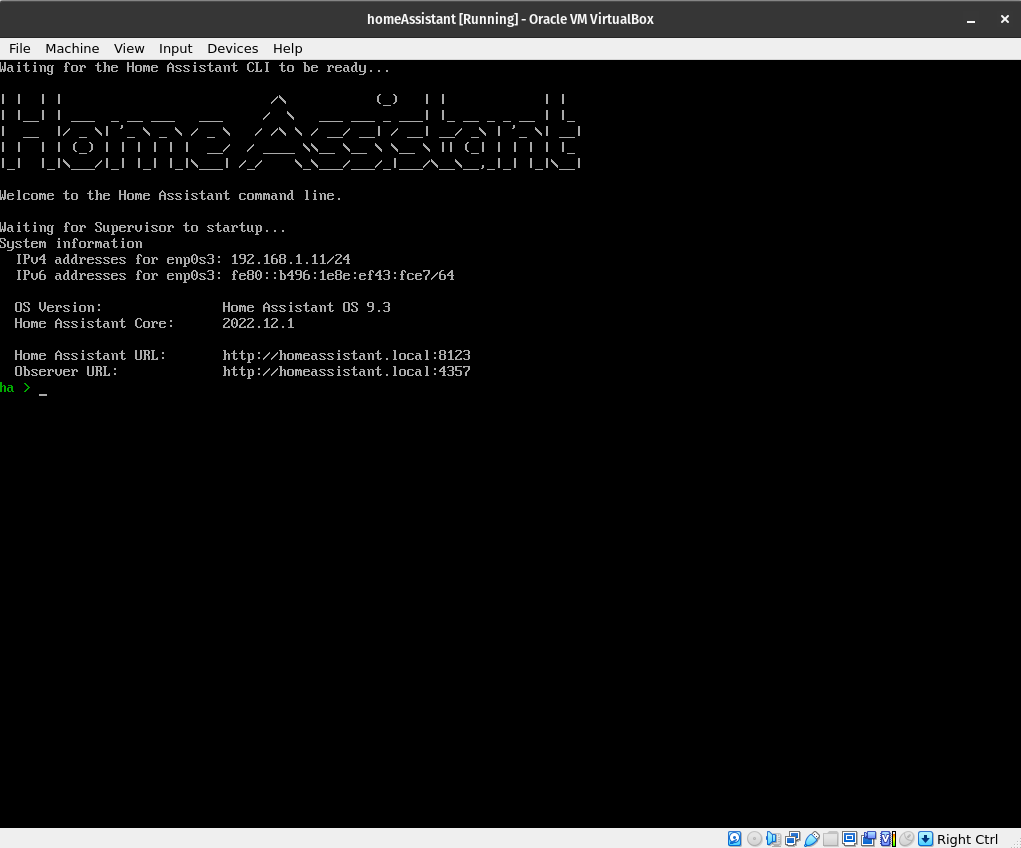
To get Home Assistant up and running i choice to add it to a virtual machine, since it was the easiest way to get it working on my pc while still having the ability to have add on’s. If you install Home Assistant with docker you can’t install add-ons.
Home Assistant running Virtual Box
Configuring sensor
To log the values from our pico to your Home Assistant. We need to have a MQTT broker enabled and then link the sensors data to Home Assistant. The way to do this is by editing the config files and adding a mqtt sensor and a template sensor.
mqtt:
    sensor:
    -   name: "mainPowerLeft"
        state_topic: "mainPower/leftMain"
        unique_id: "leftMain"
        device_class: "energy"
        unit_of_measurement: "kWh"
        value_template: "0"
        state_class: "total_increasing"
        last_reset_topic: 'fake/last_reset'
        last_reset_value_template: "1970-01-01T00:00:00+00:00"


template:
    sensor:
    -   name: "mainPowerLeft"
        unit_of_measurement: "kWh"
        device_class: energy
        state_class: total_increasing
        last_reset: '1970-01-01T00:00:00+00:00'
Important fields
- device_class: “energy”
- unit_of_measurement: “kWh”
- state_class: “total_increasing” - debated online some say “monitor”
- last_reset_value_template: “1970-01-01T00:00:00+00:00”
These are what allow you to bind with the energy dashboard. If its not setup properly this sensor will not show up as a option.
Once you have this you can add your power to the “energy” dashboard. By going to [setting] -> [Dashboards] -> [energy] -> [Add Consumption]
Then after a few hours you’ll start to get a graph like this
From here you should be all good.


